


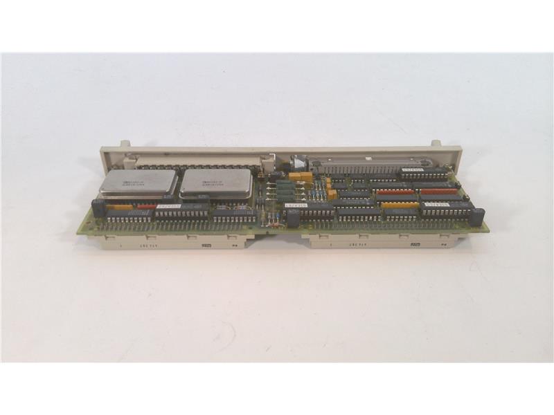

Siemens 9AP2425-2AA10 Component
The Siemens part number 9AP2425-2AA10 is a component used in industrial control systems, specifically designed for use in power distribution and transmission applications. It is a type of circuit breaker, which is a crucial safety device used to protect electrical circuits from overloads and short circuits.
Technical Specifications:
- The 9AP2425-2AA10 circuit breaker is designed to operate at a maximum voltage of 24V DC and a maximum current of 25A.
- It has a maximum breaking capacity of 25A and a maximum short-circuit current of 100A.
- The breaker is designed to operate in a temperature range of -40°C to 60°C.
Alarm/Error Codes:
The 9AP2425-2AA10 circuit breaker is equipped with a built-in alarm system that alerts operators of any potential issues. The alarm system is triggered by specific error codes, which are displayed on a user interface. The error codes are used to identify the nature of the issue and facilitate troubleshooting.
User Manuals:
The user manual for the 9AP2425-2AA10 circuit breaker provides detailed information on its installation, operation, and maintenance. It includes diagrams, illustrations, and step-by-step instructions for setting up and troubleshooting the device.
Troubleshooting:
Troubleshooting the 9AP2425-2AA10 circuit breaker involves identifying the error code displayed on the user interface and referring to the user manual for guidance. The manual provides troubleshooting procedures for common issues such as faulty connections, misaligned components, or incorrect settings.
Programming:
The 9AP2425-2AA10 circuit breaker is designed to operate in a standalone mode and does not require programming. However, it can be integrated with other Siemens devices and systems, which may require programming to ensure seamless communication and operation.
Installation:
The installation of the 9AP2425-2AA10 circuit breaker involves connecting it to the electrical circuit and ensuring proper alignment of all components. The user manual provides detailed instructions for the installation process, including diagrams and illustrations to aid in the process.